Efficiency in an assembly line is not about the components you use. It is about how well the line matches the production rhythm, the material flow, and the operators’ movements.
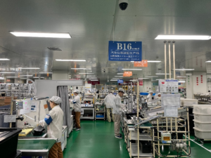
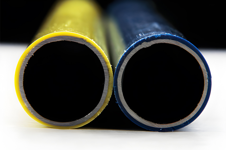
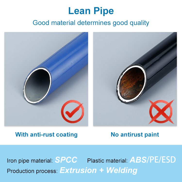
A lean pipe system gives the physical flexibility to build and reconfigure, but flexibility alone does not create efficiency. The design must start with production data and work backward to the pipe lengths, joint types, and workstation configurations. Here is how to approach that process from a production-first perspective.
Throughput Targets Determine Workstation Dimensions and Layout
The first question is not what size pipe to order. It is how many units must leave the line each shift. Takt time — the available production time divided by customer demand — sets the heartbeat for the entire design. Divide the takt time by the total assembly work content to estimate the number of workstations required.
This number drives everything else. More workstations mean a longer line and more floor space. Fewer workstations mean each station must handle more operations, which increases cycle time pressure and may require wider work surfaces or additional tooling. The layout sketch must accommodate the required station count while fitting within the available floor area. Without this calculation, you are designing blind.
Line Balancing Identifies Bottlenecks Before Assemble a Single Joint
Once you know the number of stations, break the assembly process into individual tasks. Assign each task to a station so that the total work time at each station is roughly equal and stays within the takt time. This is line balancing and is one of the most critical analytical steps. We use it to validate the station setup before starting construction.
A poorly balanced line means some operators are overburdened while others wait. The bottleneck station dictates the entire line’s output. Use a precedence diagram to map task dependencies. Then experiment with different task groupings on paper. The goal is to minimise idle time across stations.
Only when the balance is acceptable should we translate the station boundaries into physical pipe dimensions. As we carry out the balancing exercise, we may find that more stations are needed than we initially estimated, or that certain tasks can be automated or combined. This iterative process helps us refine the station layout before we finalize the physical pipe dimensions.
Material Presentation Points Dictate Pipe Placement and Reach
With station boundaries defined, the next production question is how parts reach each operator. Material presentation is not a support function — it directly affects cycle time. Every second an operator spends reaching, walking, or searching for a component is non-value-added time.
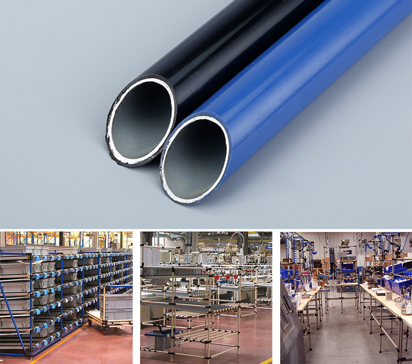
Design material supply points within the operator’s primary work zone. For light components, gravity flow racks with inclined roller tracks keep parts at the front. For heavier items, position bins or trays at waist height to minimise lifting. The pipe frame must support these presentation systems while staying out of the operator’s movement path.
Pipe placement is determined by reach envelopes. Measure the maximum comfortable reach for the 5th to 95th percentile operator. Place vertical supports outside this envelope. Horizontal pipes can support shelves, tool rails, and lighting. The layout of material presentation points also affects the replenishment route — how new parts are brought to the line. If replenishment interferes with assembly, the design fails.
Joint Selection Must Match Load Profiles, Not Just Visual Fit
Production efficiency depends on stability. A wobbly workstation slows operators and creates safety risks. The joints that connect the pipes determine structural rigidity. Selecting joints based only on availability or appearance is a common mistake.
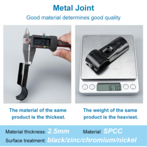
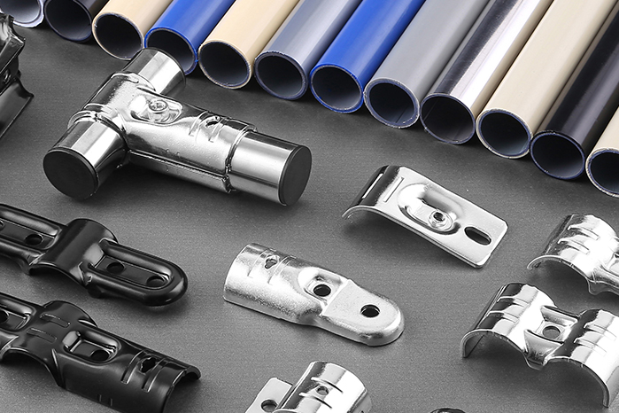
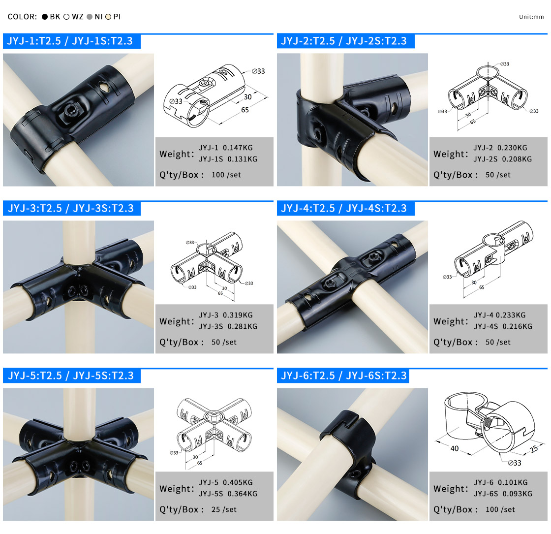
Consider the load profile at each station. Does it carry only lightweight components, or does it support heavy assemblies, fixtures, and perhaps an operator leaning on the surface? For high-load stations, specify thicker-gauge joints. Some suppliers offer joints with 2.6mm thickness for heavy-duty applications, while standard options like 2.5mm cold-hardened steel suffice for general use.
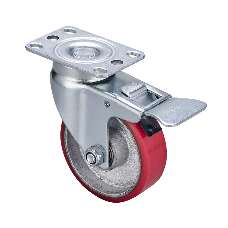
Also consider dynamic loads. If the line includes moving carts or conveyor sections, joints must withstand vibration and rolling forces. In such cases, anti-loosening set screws or locking mechanisms become essential.
The lean tube system’s modularity relies on clamping pressure, so joint design directly affects how long the structure stays tight under repeated use. Match the joint specification to the actual mechanical demands of each station, not to a one-size-fits-all rule.
Adjustability Is a Design Parameter, Not an Afterthought
The purpose of a lean pipe system is reconfigurability, but many designers treat this as a passive benefit rather than an active design feature. Build adjustability into the initial design so that future changes do not require rebuilding from scratch.
This means using standard pipe lengths that allow for height and width adjustments without cutting new pieces. Use adjustable brackets for work surfaces and monitor arms. Position vertical columns on a grid that accommodates multiple station arrangements. Over-specify the number of joints at critical connection points so that you can add cross-braces later if stiffness becomes an issue.
At Junyi, we encourage clients to think of the assembly line as a living system. The first configuration is rarely the final one. Product changes, volume shifts, and continuous improvement will demand modifications.
If the design anticipates these adjustments — with extra joint capacity, modular sub-frames, and accessible connections — the cost and time of each change drop dramatically. That is where the lean pipe system’s value truly compounds.
Validation With Real Production Data Completes the Design Loop
After assembly, run the line at full production speed with actual operators and parts. Measure cycle times at each station and compare them to the balanced targets. Watch for waiting time, operator fatigue, and material shortages. These observations often reveal issues that the paper design did not capture — for example, a reach that seems fine on drawing but becomes tiring after two hours.
Use the data to adjust. Raise a work surface. Move a parts bin closer. Add an extra roller track to smooth material flow. These tweaks are quick because the system is modular. The validation phase is not a formality; it is where the design proves itself.
For complex lines, conduct a full day’s run and collect data on output, defects, and downtime. Analyse the results against the original throughput target. If the line meets or exceeds the target with stable quality, the design is validated. If not, revisit the balance, material flow, or joint stability. The modular nature of the lean pipe system allows iterative refinement without major capital expense.
At Junyi, we see the validation phase as the final step in a production analysis, not the end of the project. The data from this phase informs the next redesign, which will come sooner than expected.
By treating the assembly line design as an analytical cycle — throughput → balance → material flow → joint selection → adjustability → validation — you turn a flexible structure into a genuinely efficient production tool. The pipes and joints are just hardware. The efficiency comes from the decisions you make before, during, and after assembly.