Automotive parts racks face three primary loads: vertical weight, lateral forces from movement and impact, and torsional forces from uneven loading or floors. The frame must withstand these forces while maintaining stability through repeated use.
A metal joint pipe frame combines coated steel pipes with precision metal joints to meet these demands. Its performance depends on effective load distribution, component strength, and secure connections.
Primary Loads Acting on Automotive Parts Racks
Vertical loads come from stored components and transfer through the shelves or supports into the frame. Lateral forces arise from starting, stopping, turning, impacts, and uneven floors, creating bending forces that the vertical members and bracing must resist.
Torsional loads occur when weight is unevenly distributed or the rack encounters uneven surfaces, placing additional stress on the connections. A reliable frame must account for vertical, lateral, and torsional loads throughout its service life.
Load Path and Potential Failure Points
Understanding the load path helps identify vulnerable areas. Vertical loads transfer from the shelves through the vertical pipes into the base frame and floor, while lateral forces pass through the vertical members and bracing into the base structure.
The connections between vertical pipes and the base frame are particularly critical because they handle both compression and bending forces. Secure joint geometry and fastening help prevent slipping, deformation, and loosening that could compromise frame stability.
Pipe Response Under Structural Loads
The pipe forms the primary structural members of the frame, while its diameter, wall thickness, material properties, unsupported length, and frame geometry influence bending resistance and column stability.
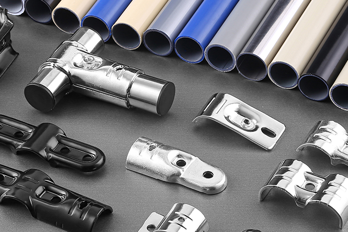
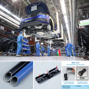
The standard coated pipe in lean tube systems has a diameter of 27.8mm ± 0.2mm and consists of welded steel with an outer plastic coating and an inner anti-corrosion layer. The inner wall of each pipe receives a specialized anti-rust spray coating that forms a tight, durable bond with the pipe interior. This interior protection is critical for automotive environments where humidity and chemical exposure are common.
During production, a critical gas test is performed on every complete lean tube — high-pressure air is injected into the pipe interior to eliminate any missed welds or perforations. This testing ensures that the pipe’s load-carrying capacity is not compromised by manufacturing defects.
For vertical loads, the pipes act primarily in compression. Buckling is the primary failure mode, and the unsupported length between joints determines the buckling resistance. Shorter spans between connections reduce the effective column length and increase load capacity.
When subjected to lateral stresses, pipes take on the role of beams or cantilevers, with the amount of bending resistance being dictated by the section modulus and yield strength of the material. This amount of bending is defined by the geometry of the frame, in particular the location of the cross-members and the diagonal braces.
Joint Response Under Vertical and Lateral Loading
The joints are where loads transfer from one pipe to another. The metal joint geometry determines how effectively these connections resist force without slipping or deforming.
Under vertical loading, the joint transfers compressive force between intersecting pipe members. The screw applies clamping pressure that compresses the joint against the pipe surface, creating friction that resists movement. Under lateral loading, the connection must resist relative movement caused by shear and bending forces. The stiffener geometry increases the contact and clamping area, while the snap-and-screw connection helps maintain positional stability.
The metal joints feature long strip stiffeners — two at the head and two at the tail, arranged in a jagged, three-column pattern. This design increases the joint’s resistance to deformation under load and prevents the connection from loosening over time. The head features a dovetail-shaped snap that connects to the lean pipe through both the snap and the screw. This combination of snap engagement and screw clamping provides both geometric and frictional resistance to movement.
Under combined loading — vertical, lateral, and torsional — the joint must maintain its clamping force and geometric alignment. If the clamping force relaxes, the joint can slip, and the frame loses its dimensional stability. The stiffener design and the screw locking mechanism work together to maintain clamping force under dynamic loads.
Bracing and Cross-Member Contributions to Stability
A frame that relies only on vertical and horizontal members will deform into a parallelogram shape under lateral loads — a failure mode known as racking. Diagonal bracing converts lateral forces into axial loads that the pipes resist more effectively.
The modularity of metal joint pipe frames allows strategic placement of diagonal braces and cross-members that improve structural rigidity. Diagonal braces reduce the unsupported length of vertical members and distribute lateral loads across multiple joints. Cross-members at the top and bottom of the frame tie the vertical members together, creating a structural diaphragm that resists torsional forces.
The frame’s overall stability depends on the arrangement of these bracing elements. A frame with adequate bracing will resist lateral deformation and maintain its squareness under movement. A frame without bracing relies solely on joint stiffness, which is insufficient for high lateral loads. The analysis must consider the bracing configuration as part of the structural system.
Roller Track Integration and Its Structural Effects
Many automotive parts racks incorporate roller tracks for material presentation or flow-through storage. Roller tracks introduce concentrated loads at their mounting points, making local frame reinforcement important.
Our Junyi load-bearing structure of iron roller tracks features substantial support capacity, while aluminum roller tracks with thicker profiles provide a lighter alternative where load requirements allow. Iron roller tracks with substantial bearing supports can handle heavier applications. Double-bearing wheels also help reduce rolling resistance and shock transmission during material movement.
When roller tracks are mounted to a metal joint pipe frame, they create localized load points that the frame must resist. The tracks transfer part weight into the frame at discrete mounting positions rather than distributing it across a shelf. This concentration of load means the frame members at the mounting points experience higher local stresses.
The frame must be reinforced at these points with additional cross-members or thicker pipe sections. The structural analysis must account for these localized loads when designing the frame layout.
Verification Through Load Testing and Quality Control
Structural analysis is theoretical until verified under real load conditions. Automotive parts racks should be tested for vertical load capacity, lateral resistance, and stability under dynamic and uneven loading.
The gas test performed on each coated pipe helps identify welding defects or perforations before assembly. Metal joints should also be checked for consistent clamping performance, screw tension, and structural integrity. Electroplated surfaces provide corrosion protection that helps preserve connection performance over time.
At Junyi, our coated pipes, reinforced metal joints, and load-bearing roller tracks work together as an integrated tube and joint systems solution. The pipes carry primary loads, the joints transfer forces, and bracing helps resist lateral deformation. Selected according to actual operating conditions, these components support frame stability through repeated automotive production cycles.